Overhead Transmission Line Lightning and Grounding Reference Book Software Applications
The following Lightning and Grounding applications are intended to be used in conjunction with Overhead Transmission Line Lightning and Grounding Reference Book. Chapter 5 provides examples on how the applications can be applied.
The applications are:
- Estimates of Soil Parameters
- Calculation of Ground Electrode Dimensions to Obtain a Desired Value of Resistance
- Calculation of Ground Electrode Resistance
- Voltage on Tower Ancillary Circuits during Phase to Ground Faults
- Potential and Step Potential near a Ground Electrode
- Influence of Ground Electrode on Lightning Performance
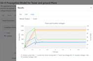
- Propagation Model for Tower and Ground Plane
- Tower Footing Dynamic Resistance
- Ionization and Propagation Model for Counterpoise
Lightning Impulse Strength Calculator
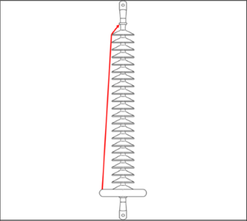
Tests performed at EPRI have shown that the lightning impulse strength of transmission line insulator strings can be well estimated using the dry arc distance of the different air gaps. With those values on hand, the calculator included in the page will help you estimate the Critical Flashover Voltage (CFO) to be used in lightning performance software.
Surge Impedance Calculator
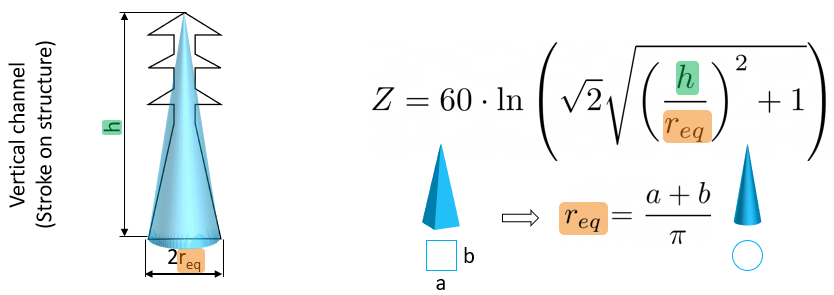
In transient simulations for lightning performance studies, the voltage and the current of the traveling wave going up and down the structure are linked by a parameter named the surge impedance. This page provides a calculator to estimate the structure surge impedance to be used in TLW-Gen2 for different shapes of structures.
US Ground Conductivity Map
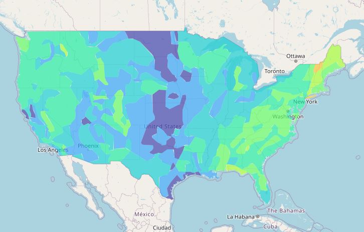
This page provides the earth resistivity for locations in the continental United States of America. The resistivity data are estimates for the near-surface layer of earth and are useful for the analysis of lightning surges and radio noise signal propagation at frequencies up to 1 MHz. The main purpose of this soil resistivity map is to indicate the overall resistivity in an area, and in this regard, it is better than a map of rock types.
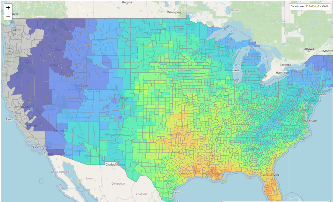
US Ground Flash Density Map
This page provides the lightning ground flash density averaged per county in the continental United States of America. The ground flash density (GFD) is the number of lightning flashes that hit the earth (or objects on the earth) per unit area (one square kilometer or square mile) and time (one year). This parameter is very important for the calculation of lightning performance of overhead transmission lines.