Calculators
Core Degradation Calculator
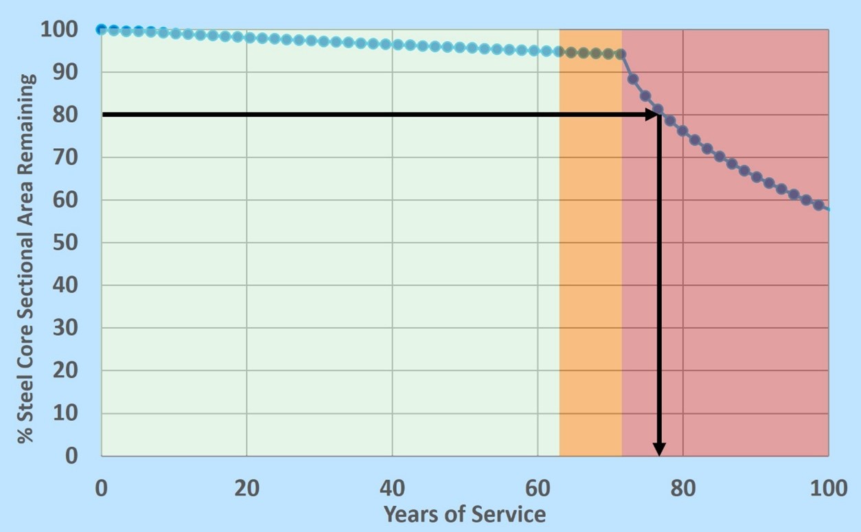
EPRI has developed an end-of life calculator for ACSR and ACSS conductors that incorporates the effects of conductor attributes (conductor type, core coating type, operating temperature…) and the surrounding environment corrosivity to determine the conductor’s estimated life span based in the steel core corrosion degradation. This information may be utilized by a utility to prioritize conductor inspection and select the right conductor for a specific location.
Research Result Summaries

Corrosion Failure of a Conductor Located Near an Industrial Site
A utility reached out to EPRI corrosion team to discuss a conductor failure that occurred near an ammonium nitrate plant. It is suspected that the conductor failure was due to corrosion. The line is located about 45 yards from the plant cooling towers.
A conductor sample taken near the failure point was sent to EPRI for condition assessment.

AAAC Flint Forensic Report
All aluminum conductor performance is not well understood in coastal and desert climates. This report provides an overview of the environmental conditions at a series of spans where a AAAC failed, identifies the type of corrosion and the cause of the failure. From this we may better understand the time to failure for a conductor in-service with similar environmental conditions.

Geometry Factor Development
Research has shown that the outer strand layers on a conductor provide some environmental protection to the steel strands. Conversely when the strand layers are opened in a “birdcage” the corrosion is accelerated on the steel strands. Both conditions have been quantified for many types of conductors and may be applied to an atmospheric corrosion rates as a correction factor. This allows engineers and asset managers to model the time to failure for conductors in their service territory.

Condition Assessment Comparison of Two Coastal Aluminum Conductors
Research into all aluminum conductor corrosion has revealed a very interesting mode of failure that is dependent upon specific environmental conditions. This report contains health assessments for two all aluminum conductors in similar environments with the 50 year old conductor in “as new” condition and the 20 year old conductor failing due to exfoliation and hydrogen embrittlement.

Corrosion Monitoring System (CMS) The Corrosion Monitoring System (CMS) has migrated from a research tool into a standalone data collection system to help us understand corrosion anomalies and monitor “at risk” structures. The CMS has its own power supply, data collection, cellular connection and a host of atmospheric and subgrade sensors to identify changes in both the environment and the degradation rate of the asset. That data may be used to model conductor degradation, ground grid degradation or any asset in atmospheric or soil exposure. Perhaps the greatest benefit of deploying the CMS is understanding severe types of corrosion such as stray current or circulating current corrosion.

Laboratory Corrosion Resistance Evaluation of Conductor Strands A utility service territory can cover a vast area, resulting in transmission lines being exposed to a wide range of corrosive environments including coastal and industrial sites. A question often asked by members is “Which conductors should I use in the most corrosive areas of my service territory?”. Although this question could be answered using field sampling of conductors and conductor inspection technologies, EPRI is currently working on measuring the corrosion resistance of individual conductor strands in a laboratory setting.
Reference Information
Videos

Forensic Analysis of Hardware due to Corrosion Damage Forensic analysis of in-service or failed hardware allows an understanding of what caused the damage. Often there are clues that uncover the type of stresses that led to performance loss such as electrical, mechanical, thermal or chemical stresses. Once the type of stress is understood, a mitigation method may be prescribed in the form of material substitution, coating system application, cathodic protection or even an inhibitor. When there are multiple stresses in combination it may require multiple mitigation methods but those must then be aligned with the environment.