Reference Information
Key information from reference documents and guides (e.g.) or succinct descriptions of concepts (e.g. what is risk and how do I visualize it)
This the multi-page printable view of this section. Click here to print.
Key information from reference documents and guides (e.g.) or succinct descriptions of concepts (e.g. what is risk and how do I visualize it)


Thermo-Mechanical Bending (TMB) Rig Extruded-dielectric underground transmission cables experience thermo-mechanical bending (TMB) during operation and daily load cycling. EPRI is investigating the impact of TMB on design, operation, and long-term performance of the extruded dielectric cables. One of the key facilities used in this analysis is the EPRI Full-Scale Thermo-Mechanical Bending/Aging Test Rig. The test rig is installed in the EPRI Laboratory in Charlotte, NC. Results from this test rig can be used in design, operation, and maintenance of such cable systems.
Mechanical Parameter Testing Extruded-dielectric underground transmission cables experience thermo-mechanical bending during operation and daily load cycling. EPRI is conducting research into their effects on the cables to aid in design of suitable cable constraint and support systems. The study is achieved first through measurements of mechanical parameters of various cable constructions, finite element analysis of the installed conditions, and then empirical verification by a full-scale test rig comprised of a length of full-sized duct. The results of the mechanical parameter tests are incorporated into finite element analysis theoretical models to assist in extruded-dielectric cable installations and designs and enhance operation and maintenance of such cable systems.
Mechanical Bending Rig Extruded-dielectric underground transmission cables experience thermo-mechanical bending during operation and daily load cycling. EPRI is conducting research into their effects on the cables to aid in design of suitable cable constraint and support systems. The study is achieved first through measurements of mechanical parameters of various cable constructions, finite element analysis of the installed conditions, and then empirical verification by a full-scale test rig comprised of a length of full-sized duct. The results of the mechanical parameter tests are incorporated into finite element analysis theoretical models to assist in extruded-dielectric cable installations and designs and enhance operation and maintenance of such cable systems.
| Test Facility | Location |
|---|---|
| Extruded Cable Thermo-mechanical | Charlotte |
| Extruded Cable Mechanical Parameter | Lenox |
| Cable Mechanical Bending | Charlotte |
| Sensor Research | Charlotte |
| Magnetic Field Shielding | Charlotte |
| Cable Failure Root Cause | Charlotte |
Description of each test facility (coming soon)
Extruded-dielectric underground transmission cables experience thermo-mechanical bending (TMB) during operation and daily load cycling. EPRI is investigating the impact of TMB on design, operation, and long-term performance of the extruded dielectric cables. One of the key facilities used in this analysis is the EPRI Full-Scale Thermo-Mechanical Bending/Aging Test Rig. The test rig is installed in the EPRI Laboratory in Charlotte, NC. Results from this test rig can be used in design, operation, and maintenance of such cable systems.
The full-scale test rig comprises of a 55-m (180 ft) long thermally insulated 210-mm (8.25 in.) steel duct with a cable section installed in the duct and constrained at both ends. The cable is heated by dc currents through cable conductor and sheath to create a thermal profile that simulates cable operating conditions at various temperature levels to simulate daily load cycling. The test rig utilizes a data acquisition system to measure and record test data throughout the test procedures. The measured test data include:
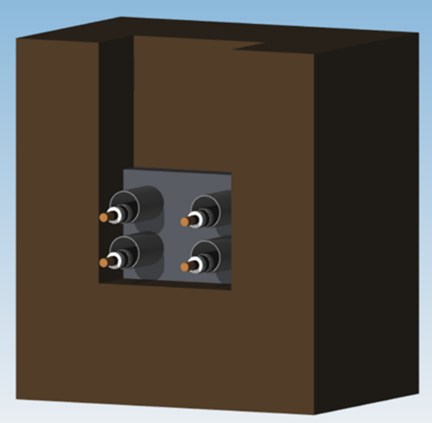
The test rig also includes a laser gauge for total test length measurement, dial gauges for measuring end movements from thermal expansion, 4000 A dc power supply for heating the cable conductor, 3000 A dc power supply for heating the cable sheath, and bundled pair optical fiber for distributed temperature measurements along the cable jacket surface. The figures below show the EPRI Full-Scale Thermo-Mechanical Bending/Aging Test Rig (left) and a view of an installed cable in the steel duct from an opened hatch section (right).


Extruded-dielectric underground transmission cables experience thermo-mechanical bending during operation and daily load cycling. EPRI is conducting research into their effects on the cables to aid in design of suitable cable constraint and support systems. The study is achieved first through measurements of mechanical parameters of various cable constructions, finite element analysis of the installed conditions, and then empirical verification by a full-scale test rig comprised of a length of full-sized duct. The results of the mechanical parameter tests are incorporated into finite element analysis theoretical models to assist in extruded-dielectric cable installations and designs and enhance operation and maintenance of such cable systems.
The EPRI Extruded-Dielectric Transmission Cable Mechanical Parameter Test Rigs measure four key mechanical parameters of extruded-dielectric cables: bending stiffness, coefficient of thermal expansion, axial stiffness, and torsional stiffness. The bending stiffness testing evaluates the ability of the cable to resist lateral bending at right angles to the cable longitudinal axis. The coefficient of thermal expansion testing observes changes in length of a cable per unit change in conductor temperature. The axial stiffness testing assesses the ability of the cable to resist and exert longitudinal forces as a result of thermal expansion and contraction from the heating and cooling of the conductor. The torsional stiffness testing measures the ability of the cable to resist twisting along the longitudinal axis of the cable. Each parameter is measured with the cable at multiple operating temperatures ranging from ambient to 105°C.
The mechanical parameter test rigs, located in the EPRI Lenox Laboratory, utilize various test equipment including load cells, actuators, displacement sensors, and data acquisition systems. The images below show the setups of the different mechanical parameter rigs (Bending Stiffness – left; Torsional Stiffness – middle; and Axial Stiffness and Coefficient of Thermal Expansion – right).

Underground transmission cables experience thermo-mechanical bending during daily load cycles. EPRI investigates the impact of such thermo-mechanical forces and bending on design, operation, and long-term performance of underground transmission cables. One of the test setups used in this analysis is the EPRI transmission cable mechanical bending rig. The test rig is installed in the EPRI Laboratory in Charlotte, NC. Results from this test rig can be used in design, operation, and maintenance of such cable systems.
The purpose of the test rig is to perform accelerated aging tests on select cable samples through cyclical bending. The test rig comprises of a metal bed and a mock pipe wall with the cable sample constrained at both ends. The cable sample is clamped at the cable conductor on each end and tension and compression force is applied axially to one end of the conductor until a bend forms and the cable touches the mock pipe wall. The force is recorded at the mock pipe wall and once the user defined force is met, the actuator retracts, and the cable is pulled straight completing one cycle. The cable sample is restricted to a single plane to achieve repeatable, localized bending. The applied force is monitored using load cells situated at the driving actuator and the mock pipe wall. The test rig bends and straightens the cable sample for 30,000 cycles to simulate a service life of 40 years.
After the bending test is complete, the cable sample is analyzed layer-by-layer for signs of degradation or damage resultant from the cyclical motion. Visual inspection and material analysis are performed for each critical layer, such as, outer jacket, metallic shield/sheath, insulation, and conductor. The material analyses include factors that may affect the life expectancy of a cable.
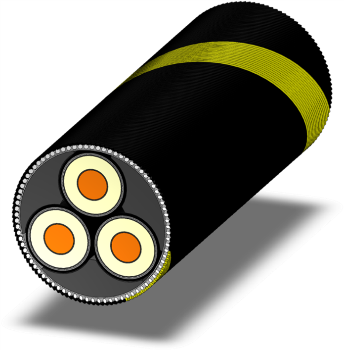
The test rig includes a data acquisition system to measure and record test data during the testing and operation. Guide rails and cable restraints are adjusted to meet the cable testing requirements of different cable types and construction. The figures below show the EPRI transmission cable mechanical bending rig (left) and a side view of the installed extruded transmission cable sample (right).
In summary, functions of the mechanical bending test rig include:


