Drone Detection Testing in Lenox
This document outlines the test and evaluation plan for a drone detection system (DDS) intended for deployment in electrical substations. The plan focuses on assessing the system’s performance, reliability, and operational characteristics in various simulated and real-world substation environments.
Latest edition of the Field Guide (Substations), as well as a collection of other topics such as Facial Recognition, general security concepts, etc.
This document outlines the test and evaluation plan for a drone detection system (DDS) intended for deployment in electrical substations. The plan focuses on assessing the system’s performance, reliability, and operational characteristics in various simulated and real-world substation environments.
Time at Site: 7:30 AM – 6:00 PM each day, plus one night testing session.
0.3.1. Document Installation requirements (power, network, physical footprint), setup time, tuning, and configuration.
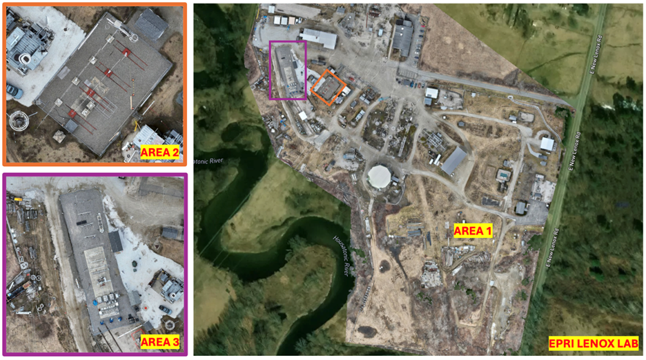
1. Assessment 1 – Open Field Evaluation (Area 1) Objective: Evaluate the vendor’s technology in an open field environment to establish baseline performance and operational behavior.
1.1. Setup and Configuration
1.1.1. Vendor installs the system at the designated open area location.
1.1.2. Perform initial configuration and calibration flights. Confirm normal operation with the vendor.
1.2. Performance Data Collection – Main data point is a “Yes/No” for how the system detects and/or identifies the UAS (drone 1 and drone 2).
1.2.1. Fly UAS route at 200 ft AGL, starting approx. 50 meters from the center point and ending up directly over the system.
1.2.2. Repeat step 1.2.1 five times for each of the two drones.
1.2.3. Fly UAS route at 400 ft AGL, with similar start and end points; hold position above system for 1- 2 minutes.
1.2.4. Repeat 1.2.3 five times for each of the two drones.
Additional Tests
1.2.5. Drone 3 - Autonomous Drone Testing (Drone Dock): Record flight patterns (tangential, vertical, lateral, angled, circular, etc.), and trigger the mission. Note dock distance and detection performance.
1.2.6. Simultaneously launch two drones ~50m from the system (e.g., 200ft and 400ft AGL) and observe behavior.
1.2.7. Document the classification of the system, threat level confidence, and other system-reported parameters.
1.2.8. Configure and test alarm response to detection events.
1.2.9. (If time permits) Expand tests to different altitudes and distances:
NOTE: Assessment sequence may change based on operational needs and system readiness.
2. Assessment 2 – De-energized UAS Test Yard (Area 2) Objective: Evaluate system performance in an environment surrounded by metal infrastructure while the yard is de-energized.
2.1. Installation
2.1.1. Vendor installs technology in the designed location in/around the UAS test yard. Note: The setup remains same for non-energized and
energized conditions. Hence the initial deployment location assumes that it will remain the same for energized testing too.
2.1.2. Perform initial configuration and calibration flights. Confirm normal operation with the vendor.
2.2. Performance Data Collection – Main data point is a “Yes/No” for how the system detects and/or identifies the UAS (drone 1 and drone 2).
2.2.1. Repeat steps 1.2.1 to 1.2.9
2.3. Clutter-Specific Flight Path
2.3.1. Design flights where the drone passes behind or between large metallic structures (e.g., transformers, support structures) to test detection in occluded or high-multipath scenarios.
2.3.2. Evaluate detection continuity, reacquisition time if track is lost, and impact of multipath reflections.
3. Assessment 3– Energized UAS Test Yard at High Voltage (Area 2) Objective: Evaluate system performance within-in a high voltage environment (with corona and/or arcing).
3.1. Assumes technology already in the UAS test yard at the designated spot and configured.
3.2. Energize the UAS Test Yard to 100 kV
3.2.1. Verify with the vendor that the technology is working as normal. Also, monitor the system for any EMI-induced false alarms or errors without any drones present.
3.3. Performance Data Collection – Main data point is a “Yes/No” for how the system detects and/or identifies the UAS (drone 1 and drone 2).
3.3.1. Repeat steps 1.2.1 to 1.2.9
4. Assessment 4– Energized UAS Test Yard at High Current (Area 2) Objective: Evaluate system performance with-in a high-current environment (optional corona and/or arcing).
4.1. Assumes technology already in the UAS test yard at the designated spot and configured.
4.2. Energize the UAS Test Yard to 750 A.
4.2.1. Verify with the vendor that the technology is working as normal.
4.3. Performance Data Collection – Main data point is a “Yes/No” for how the system detects and/or identifies the UAS (drone 1 and drone 2).
4.3.1. Repeat steps 1.2.1 to 1.2.9
5. Assessment 5- Energized 138kV Research Substation (Area 3) with Staged Scenarios Objective: To evaluate how the vendor’s drone detection and classification system operates in a fully energized, operational substation environment (outside the Lenox 138 kV yard) under staged environmental conditions and with varied aerial targets. The goal is to assess detection reliability, classification accuracy, confidence levels, and notification/alarm behavior in more realistic edge cases.
5.1. Installation
5.1.1. Vendor installs technology in the designed location (e.g., on a pole outside the perimeter of the 138kV research substation, Area 3).
5.1.2. Perform initial configuration and calibration flights. Confirm normal operation with the vendor.
5.2. Autonomous Drone and Night Testing
5.2.1. Conduct a baseline test flight using autonomous drone during daytime conditions.
5.2.2. Repeat the same flight routes under nighttime conditions to assess system performance in low light. If any challenges with autonomous mission, the drone will be turned to manual controls as a backup choice.
5.2.3. Add a suspended box to the drone and perform a flight path. Note the threat level and IR camera capture capabilities.
5.3. Environmental Interference Testing
5.3.1. Activate rain spray system to simulate fog or mist within the 138kV yard.
5.3.2. Fly the drone behind the fog and observe system detection accuracy.
5.4. Object Classification Testing
5.4.1. Fly a bird-like drone to mimic bird flight. Record system classification output and check for false detection.
5.4.2. Introduce non-drone objects such as balloons and kites (safely away from energized equipment) into the airspace. Observe whether they are detected, ignored, or misclassified. (Aluminum and Latex)
5.4.3. If natural bird activity occurs, monitor and document the DDS response (detection, classification, alarm).
5.5. Threat Level Confidence Analysis
5.5.1. Fly two types of drones (Drone 1 and Drone 2) at multiple distances from the system. Document the threat level reported and associated confidence values (%).
5.6. Alarm and Notification Functionality
5.6.1. Configure alarms and/or notifications when the drone is detected.
5.6.2. Triger system alerts via drone flights. Evaluate how alarms are delivered (visual, audible, remote notifications). Note latency and reliability.
5.7. Altitude Range Test
5.7.1. Fly drones at altitude above 400 ft AGL, particularly over and beyond the transmission gantry. Note: Real time flight data will be monitored (ADS-B).
5.7.2. Confirm if the system maintains detection and correct classification at high elevations.
5.8. Speed Variation Test
5.8.1. Fly drones at varying approach speeds: slow approach (hover/drift), moderate cruising, fast direct approach.
5.8.2. Document how the system handles tracking, detection continuity, and response.
5.9. Maximum Detection Range Test
5.9.1. Fly drone directly away from the system at a set altitude until detection is lost. Record distance.
5.9.2. Fly drone directly towards the system from beyond expected range until detection is acquired. Record distance.
5.10. Minimum Detection Altitude Test
5.10.1. Fly drone at very low altitudes (e.g., 10ft, 20ft AGL, respecting safety) to check for ground clutter effects or low-altitude blind spots.
5.11. Drone Hovering at Edge of Range:
5.11.1. Test detection of a drone hovering for an extended period at the suspected edge of its detection range.
5.12. Small Drone and DIY Drone Test:
5.12.1. Test with a significantly smaller drone (e.g., FPV drone) and DIY drone to assess sensitivity.
5.13. System Reliability & Failures:
5.13.1. Disconnect or simulate a failure of one of the system’s sensors/components (if technically feasible and safe to do so with vendor guidance).
5.13.2. Observe and document the system’s response (e.g., does it continue functioning with degraded capabilities? Does it provide an immediate error notification? Is the affected sensor clearly identified?)
5.14. Check Self-Diagnostics and Health Monitoring:
5.14.1. If possible, demonstrate the system’s self-diagnostic features and health monitoring capabilities.
5.14.2. Document the types of health parameters monitoring and how users are notified of potential maintenance needs or failures.
5.15. Automated Report Generation
5.15.1. Demonstrate the system’s ability to generate automated reports. Review the generated report for accuracy, drone flight paths, timestamps, and other relevant metadata for security audits.
Additional Questions:
Communication Requirements: What are the core communication protocols and bandwidth needs for your system?
Cybersecurity: What cybersecurity measures are implemented for your system’s hardware and software?
Data Logging: What data is logged by the system, and in what format is it available for forensics?
Ease of Use: How would you describe the typical setup, monitoring, and reporting workflow for your system?
Installation Expectations: What are the typical physical installation requirements and coverage area for a single unit in a field deployment?
Integration Ease: What are the primary methods or interfaces for integrating your system with existing security and operational infrastructures?
Maintenance: What is the recommended routine maintenance schedule and required effort for the system?
Operating Limits: What are the defined operating limits for environmental factors like wind, precipitation, and temperature?
Safety: Are there any specific safety considerations or potential hazards associated with your system’s operation or installation?
Reporting & Evaluation
Data Collection:
Logs and media from drones and detection system, video recordings and images from cameras and GoPros, screen recordings, screenshots, and real-time alerts will be reviewed.
Log Dates, temperature, general wind and weather, observations
Weather data from the weather stations around the substation area and METAR/ASOS/TAF from nearest airport.
Hardware specifics, Installation time, and vendor installation requirements will be noted down.
Detection and identification results and any general observations will be noted down.
Electric voltage, current applied, and any Corona/arcing will be noted down.
Other data as needed.
Analysis: Compare the detection results to actual drone flight paths and conditions.