Research Result Summaries
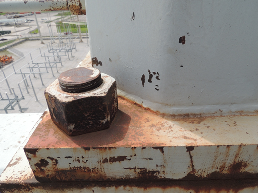
Substation H-Frame Inspection Report: EPRI was asked to provide a condition assessment of an H-Frame within a substation. The survey consisted of understanding the present condition, the weld integrity, the material loss through corrosion and the penetration rate of the pits.
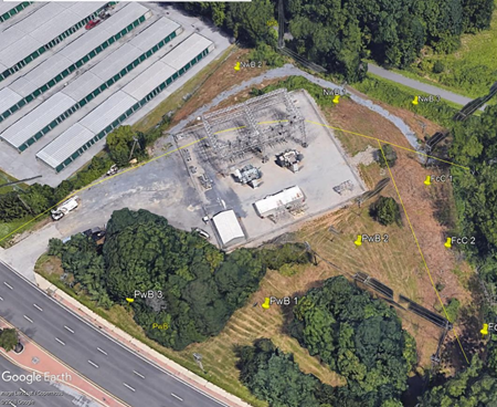
Substation Ground Grid Corrosion Study 1: Gaps were identified within IEEE Std 81 “Guide for Measuring Earth Resistivity, Ground Impedance, and Earth Surface Potentials of a Grounding System” for identifying and locating corrosion damage within substation ground grids. To satisfy these gaps, EPRI has been developing methods based on soil characterization and electrochemistry to augment the existing methodology.
Substation Ground Grid Corrosion Study 2: Gaps were identified within IEEE Std 81 “Guide for Measuring Earth Resistivity, Ground Impedance, and Earth Surface Potentials of a Grounding System” for identifying and locating corrosion damage within substation ground grids. To satisfy these gaps, EPRI has been developing methods based on soil characterization and electrochemistry to augment the existing methodology.
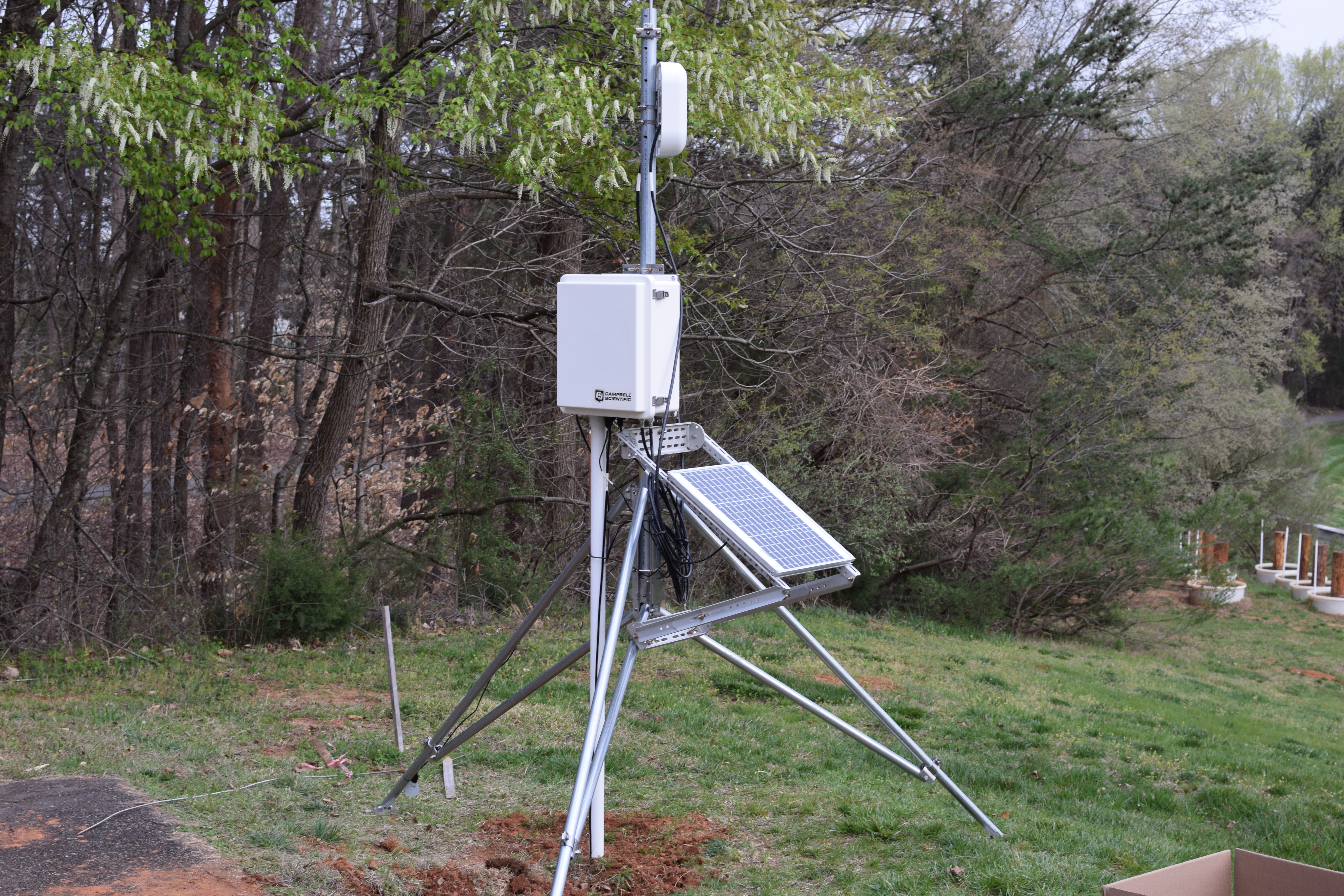
Corrosion Monitoring System (CMS): The Corrosion Monitoring System (CMS) has migrated from a research tool into a standalone data collection system to help us understand corrosion anomalies and monitor “at risk” structures. The CMS has its own power supply, data collection, cellular connection and a host of atmospheric and subgrade sensors to identify changes in both the environment and the degradation rate of the asset. That data may be used to model conductor degradation, ground grid degradation or any asset in atmospheric or soil exposure. Perhaps the greatest benefit of deploying the CMS is understanding severe types of corrosion such as stray current or circulating current corrosion.
Reference Information
New Life Cycle Decision Tools for Asset Managers, Engineers and Maintenance Personnel
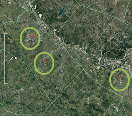
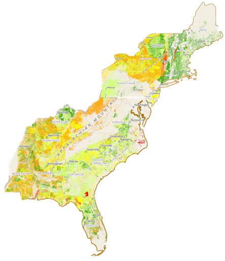
Screening a service territory for “at risk” substations and transmission line structures requires knowledge of the environmental factors and how those factors impact the structural integrity. That potential damage is categorized by severity and visualized by colors in the steel, zinc and copper soil corrosivity maps and models.
GPS coordinates for Substations or Transmission line circuits may be cross referenced to the soil corrosivity maps to determine the corrosion rate severity for that asset. This empirical data allows a utility to choose between various preventative or corrective maintenance philosophies and optimize their O&M budgets by modeling their asset condition.
EPRI soil corrosivity maps have been developed by characterizing soils in the laboratory which are then validated by health assessments in a field survey. This practice provides utilities the confidence that their asset management models are accurate due to a high confidence level and a low margin of error.
Technical Notes:
- There are some technical issues accessing the maps with certain browsers such as Microsoft Edge and Google Chrome, IT is reviewing the issue but access with FireFox is functional.
- All utilities that wish to have viewing privileges must contact Charles Le (chle@epri.com) to obtain ArcGis Enterprise access on the EPRI servers.
Videos
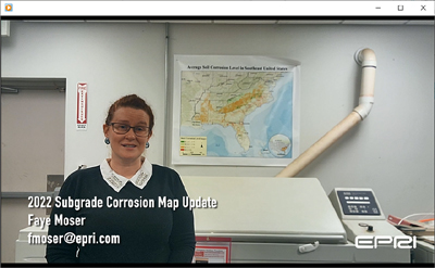
Subgrade Corrosion Map Update Screening your service territory for structures at risk has become an important tool for asset managers, engineers and maintenance crews. GIS Enabled, Subgrade corrosivity maps allow utility personnel to query circuits with severe corrosion and proactively manage the degradation due to soil exposure.
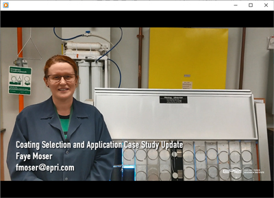
Coating System Selection and Application: Case Study Update: Coating system formulations evolve and change due to environmental restrictions and performance improvements. Evaluation by a third party is key to understand if the repair coatings are compatible with the old coating system and if the coating will perform well in different environments. The EPRI Coating Selection and Application library is migrating to a WebApp on the Transmission Resource Center so that utilities may quickly review more than 80 coating formulations and select the appropriate one for the utility needs.
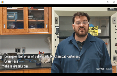
Corrosion Behavior of Sub-Grade Mechanical Fasteners Most mechanical fasteners contain multiple alloys and each metal alloy corrodes at a different rate causing a loss of structural integrity. Laboratory evaluation of each fastener allows an understanding of the impact of different stresses but also how that fastener will fail in service. Utilities may then use this knowledge for fastener selection but also to determine inspection cycles for the substation grounds.
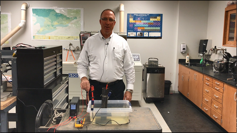
Cathodic Protection and the Effects of Stray Current In many cases the voltage level of stray currents that are found within the ROW fall below the safety criteria for touch and step potentials, so it is ignored and the effects are not well understood. This can be a fatal flaw in the asset management processes and discharge current may severely reduce the service life of a structure. This video demonstrates the concepts of anodic and cathodic interference and how we may identify each source to mitigate the stray current interference.