Guidebooks and software related to station ratings and life extension of substation assets
Annual Research Portfolio Projects
![]()
![]()
![]()
Station Ratings and Asset Life Extension
![]()
This the multi-page printable view of this section. Click here to print.
Research & Technical Content
Research Result Summaries, Reference Information, Videos, Calculators
- 1: Arresters
- 2: Batteries
- 3: Robots and Drones
- 3.1: Functional Specifications for a Substation Robot
- 3.2: Test Plan for evaluating substation robots
- 4: Station Ratings and Asset Life Extension
- 5: Calculators
1 - Arresters
Research related to selection, application, and monitoring of arresters
Substation Arrester – Overview of Ongoing Research
Substation Surge Arresters: Performing a Laboratory Diagnostic Test
Surge arresters play a key role in controlling overvoltages in the electrical power system. They are usually installed close to critical or expensive equipment, such as power transformers, to protect them from excessive overvoltages. Although worldwide service experience on station class surge arresters has shown them to be very reliable, in the U.S. there have been a number of surge arrester failures which prompted a renewed interest among EPRI members to find effective and practical tools and methods by which they can manage their surge arrester population to identify and remove high risk units before failure. The focus for this report is on condition assessment methods for surge arresters and, more specifically, on off-line methods that may be used when the arrester is disconnected or removed from service. Two laboratory test methods, a high-voltage alternating current test to determine the knee-point voltage of the arrester, and a high-voltage direct current test to measure the current at the maximum continuous operating voltage, are described in detail together with the criteria to be used for evaluating the condition of the arrester.
Station Class Metal Oxide Surge Arrester: Guidelines for Selection, Application, and Monitoring
The electric power industry is experiencing a rapid decline in available expertise, as the equipment subject matter experts reach retirement age, and few new engineers are trained to follow in their footsteps. This disappearing knowledge base has left fewer individuals with detailed selection, application, maintenance, and condition assessment expertise. Therefore, it is critical that as much of this expertise as possible be recorded. This document provides utility substation engineers with a technical resource for the selection, application, maintenance, and condition monitoring of surge arresters. This document focuses specifically on the gapless metal-oxide technology, as it represents most of the new arresters installed in transmission systems. The aim with this report is to document the functioning, selection process, failure, and degradation modes of gapless metal oxide surge arresters and to describe various condition monitoring techniques. Also, a general background information on metal oxide arresters and their functioning is provided.
Life Extension Guidelines: Station Class Surge Arresters and Instrument Transformers
Utilities are under increasing pressure to maintain service reliability while operating aging transmission substations with leaner maintenance budgets and fewer experienced personnel. A structured life extension program can help utilities make equipment maintenance, replacement, and refurbishment decisions that ensure safe, reliable, and cost-effective operation of transmission substation equipment.
These guidelines incorporate the experience of utility, consulting, and equipment engineers allowing utilities to compare their methods with the generic approaches. The three main purposes of are:
- Establish a maintenance methodology that provides a systematic approach to maintaining
- substation equipment.
- Provide strategies to assess the condition of equipment.
- Provide a decision-making approach to the evaluation of equipment for replacement or refurbishment.
These guidelines are intended to be used in conjunction with a utility’s in-house procedures and to supplement industry standards and manufacturers’ recommendations. Where in-house procedures are minimal, these guidelines can form the basis for extending existing maintenance practices into a condition-based system.
These guidelines focus on surge arresters and instrument transformers.
- Surge arresters considered in this guide are station arresters and intermediate arresters. Distribution arresters are not covered in this document.
- Overall design and types of instrument transformers in this guide are freestanding current transformers used for metering and control, voltage or potential transformers, and capacitive coupling voltage transformers (CCVTs)
2 - Batteries
Research related to battery monitoring system performance assessment
Ongoing Substation Battery Research
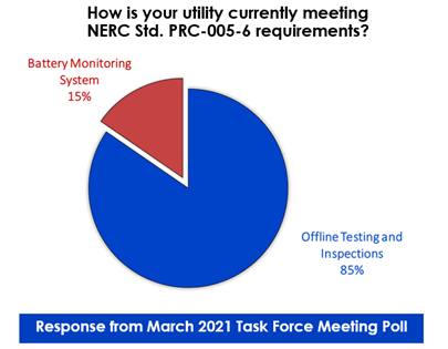
Motivation
Numerous advantages have been attributed to battery monitoring systems: they provide early notification / visibility of poor performing batteries, allow substation owners operate their batteries up to the true end-of-life, rather than replace it early, and reduce the number of routine inspection and maintenance visits thus reducing O&M costs. Several battery monitoring systems claim to be complaint with NERC Standard PRC-005. The cost of these monitor systems tends to be high relative to the cost of the batteries themselves therefore, utilities need to be sure about the performance of the monitoring systems before they decide about deploying them in the field.
EPRI with its new battery research area in Charlotte PDU Laboratory intends to explore the various aspects related to the performance of battery monitoring systems, to answer the critical question of whether these devices live to their promises.
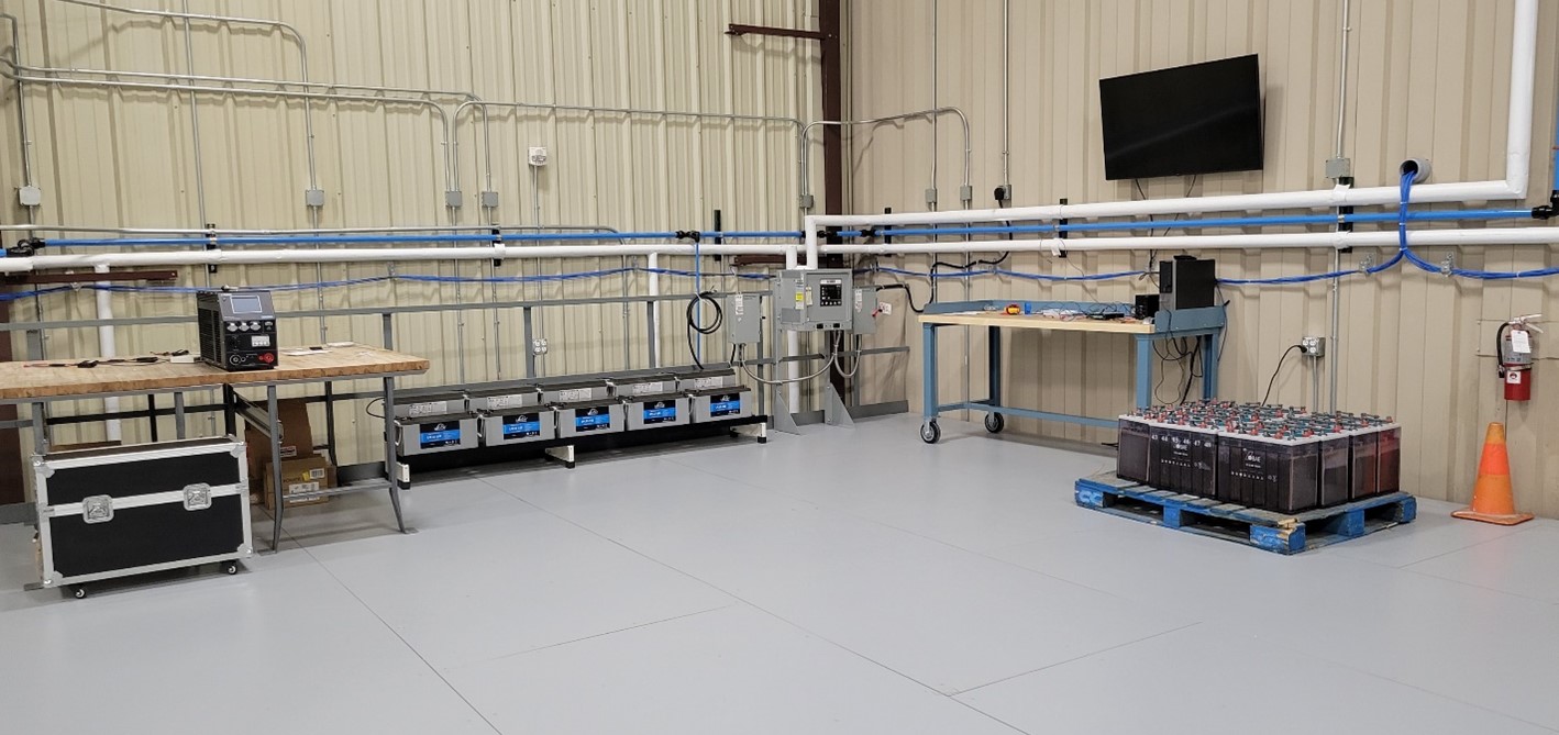 Battery Research in the Charlotte PDU Laboratory
Research Approach
Several steps are planned to provide as much information as possible about the performance of battery monitoring systems (see Figure 2). Each step will add an important piece of information to help utilities make informed decisions.

Battery Monitoring System Evaluation Plan
Experimental work
The following are the components for the laboratory performance assessment.
Battery types:
- New VLA and VRLA batteries
Battery monitoring systems:
- Battery DAQ (Sentry 1012 system)
- Eagle Eye (CGS3-100-02V system)
- Exponential Power SBS-Equalink
Member support
The research would greatly benefit from members pilot program information.
If you are able to share insights about your battery monitoring system pilot program, please contact Colleen Konsavage
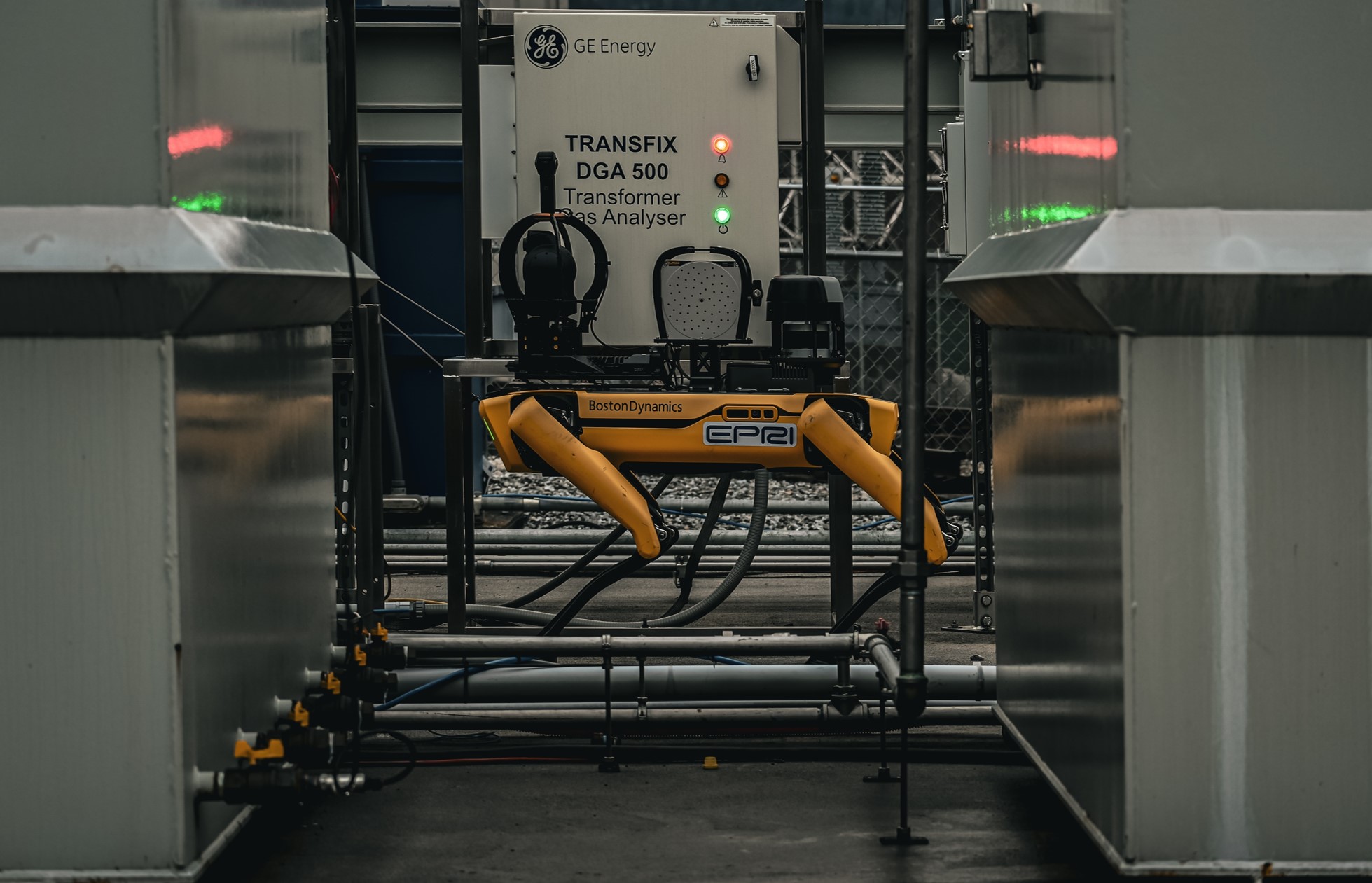
3 - Robots and Drones
Research related to robotics and drone substation applications
Functional Specifications for a Robot for Substation Inspection This document outlines the functional specifications for a robot for substation inspection applications, member ratings, vendors rating, and vendor evaluation for enhanced visual inspection in substations.

Test Plan for evaluating substation robots This document outlines the test plan for evaluating a substation robot platform designed for asset inspections. The test plan is structured on a day-by-day basis, spanning five days and including a night testing session. The robot will be evaluated across various categories such as obstacle avoidance, navigation through diverse terrains, detection of staged defects, performance in rain, and functionality during night-time operations.
Meeting Materials
WebEx Project Update: Virtual Robotics Demonstration and Vendor Interview - 23rd May 2024
3.1 - Functional Specifications for a Substation Robot
Introduction
Substation inspection is crucial for grid reliability. In 2020, EPRI and project members evaluated four robotic platforms for this purpose. For more information, please visit the project website and refer to the technical report. Now, with technology advancing, EPRI has relaunched the project to explore autonomous robots' potential alongside human inspectors. EPRI is currently assessing various robotics platforms for substation use, including new offerings and updated models. To streamline this process, EPRI is developing functional specifications in collaboration with members and robot manufacturers to align with project goals and meet industry needs.
Functional Specifications
This section outlines the functional specifications for an autonomous substation robot designed to enhance visual inspection alongside human inspections. EPRI Subject Matter Experts (SMEs) and utility researchers have collaboratively developed comprehensive functional specifications, encompassing both essential and desired features for a substation robot platform to execute autonomous operations effectively. These specifications are structured into 9 categories, comprising a total of 51 sub-features:
- Installation & Setup: A quick setup time and long runtime are important features for the robot to increase its usability. This feature also covers the communication setup of the robot.
- Teleoperation and control: This category deals with features for manual operation of the robot by an operator. It includes both in-person and remote operation, taking control of the robot in the middle of an autonomous task and stopping the robot in case of an emergency.
- Docking and Charging: It is vital that the robot can eliminate the human in the loop by charging itself up after completing a mission. Hence EPRI is looking at features like self-docking and auto-return to home for the robot.
- Autonomous Navigation: To make the robot independent of a human operator, it must be able to perform tasks autonomously. This includes performing scheduled tasks in either areas mapped before, or completely unknown environments using the robot’s onboard sensor suite.
- 24/7 Operation: Substations may require the robot’s inspection capabilities at any time of the day and during any weather conditions outside. Therefore, the robot must be able to work in difficult conditions like at nighttime, adverse weather conditions, or challenging environmental landscapes like gravel or mud.
- Openness & Integration: A robot supporting 3rd party software development is always a bonus for the end user. Integration with open-source software such as ROS or Docker tremendously increases the potential value of the robot for the user.
- Payloads & Data Storage: Since the robot is being used for inspection tasks, payloads play a big part. Support for a variety of payloads, from PTZ cameras to microphones, is an asset to the user. Since users are concerned about the privacy issues linked to data collection, it is also important to understand how and where the collected data is stored by the robot.
- Safety & Alarms: The robot being deployed in dynamic environments requires a few robust methods for protecting both itself and those within its operating vicinity. This can be achieved by using both alarms to catch attention as well as using robust obstacle avoidance techniques and geofencing.
- Other: This section includes a few miscellaneous features such as the robot’s capability to operate in EMFs and maintenance requirements.
Below figure shows the distribution of functional specifications into features and sub features.
For more detailed explanation for each feature and sub feature is provided in the spreadsheet Functional specification document or use the interactive plot below. Just hover on to each category and it will pop up an explanation to each category.
Member Ratings
The functional specification document was provided to each utility lead during the task force in Feb. 2024, who were then asked to rate each sub-feature/technology using the following rating system as shown in the table below.
| Research/Pilot phase | Rating System |
|---|---|
| I know I need that | 4 |
| I think I'm going to need this | 3 |
| I may want this | 2 |
| I don't think I need this | 1 |
| I know I don't need it | 0 |
Each utility lead, along with their team, provided their input based on this rating system. The ratings were averaged based on utility. For example, if two members from Utility X participated in rating the specifications then their average rating was taken as utility X rating. Later, the ratings were averaged across all the utility ratings. Figure below shows the member utility rating for each feature.
The ratings were further categorized into three priority levels i.e., High, Medium, and Low based on the following criteria as shown in the table below.
| Ratings | Priority |
|---|---|
| >3 | High |
| 2.5> & <= 3 | Medium |
| <= 2.5 | Low |
Among the 51 features members rated 21 as high priority (required features), 20 as medium priority (desired features), and 10 as low priority (not required). The final categorization based on priority was color-coded and displayed in the interactive plot below.
Vendor Ratings
EPRI conducted interviews with 4 different vendors from around the world., some of which have branches in the US. The interviewed vendors include ANYbotics, Clearpath Robotics, Indro Robotics, and Unitree Robotics. During the interviews vendors were given the opportunity to demonstrate their robot capabilities, with some vendors even providing live demos with their robots in office environments.
Vendors were then asked to rate their robot’s capabilities for each feature using the following rating system shown in Table below.
| Response | Rating |
|---|---|
| This feature is available in our software, and we could demo it | Fully implemented |
| This feature is beta stage, and we could demo this feacture as beta version | In development |
| Thies feature in not available in our software, and it is part of our road map | Planned |
| This feature in not available or not in our road map but can be customized | Needs customization |
| We do not have this feature and are not planning tp have it in future | Not applicable/not supported |
The vendor ratings provide insights into the availability and development stage of different features within their product offerings. Please use the interactive plot below which allows you to hover and click onto each feature and category to see Vendor Ratings and are color-coded and displayed.
Evaluation
EPRI utilized a specific approach to evaluate the vendor responses alongside member ratings. The vendor ratings, originally provided as qualitative responses, were translated into numerical values as follows: Fully Implemented – 4, In development – 3, Planned – 2, Needs customization – 1, Not applicable/Not supported – 0.
| Rating | Rating System |
|---|---|
| Fully implemented | 4 |
| In development | 3 |
| Planned | 2 |
| Needs customization | 1 |
| Not applicable/not supported | 0 |
To calculate the final evaluation scores, member ratings and vendor ratings were multiplied by the average member rating for each category, using the following formula:

The resulting evaluation score were plotted in an interactive plot that allows users to hover over each vendor name to view their vendor ratings. The scores were color-coded for clarity.
| Vendor | Payloads & Data Storage | 24/7 Operation | Autonomous Navigation | Docking and Charging | Installation and Setup | Openness & Integration | Other | Safety and Alarms | Teleoperation and control | Grand Total |
|---|---|---|---|---|---|---|---|---|---|---|
| Unitree Robotics | 117.6 | 70.2 | 66.4 | 60.8 | 46.2 | 29.2 | 41.6 | 74 | 50.2 | 556.2 |
| ANYmal Robotics | 104.6 | 70.2 | 66.4 | 57.45 | 46.2 | 24.8 | 48.6 | 74 | 50.2 | 542.45 |
| Indro Robotics | 108.95 | 57.45 | 66.4 | 46.25 | 46.2 | 40.2 | 47.6 | 57.35 | 50.2 | 520.6 |
| Clearpath Robotics | 101.05 | 46.1 | 56 | 60.8 | 40 | 31.35 | 27.45 | 50.6 | 50.2 | 463.55 |
3.2 - Test Plan for evaluating substation robots
Introduction
Substation inspections are critical for maintaining reliable and safe power delivery. Traditionally, these inspections are conducted by human personnel, but with advancements in robotics technology, exploring the potential of autonomous mobile robots for this task is becoming increasingly relevant. This project aims to investigate the feasibility of integrating robots into substation asset inspections and physical security.
Objectives
This project focuses on evaluating how autonomous mobile robots can complement existing inspection practices. Through a series of research questions, the project will explore the following objectives:
- Given today’s technology, are robots complementing or supplementing human inspectors?
- Can robots be shared between multiple substations? Can robots be used portably rather than being stationed within a substation?
- Can we deploy robots in a truck and have them navigate in an unsupervised fashion, mimicking human behavior?
- What level of human involvement is required? By addressing these objectives, this project seeks to assess the potential of robots to improve substation inspections, potentially leading to increased efficiency, improved data collection, and enhanced safety for human personnel.
Testing Duration and Location
EPRI has followed a systematic approach to evaluate vendors. Each vendor would be tested for one week with five days and one night testing.
Testing Location
The testing area will mainly be in the 138 kV Research Substation. Parts of the testing may be on the EPRI Lenox Campus. Figure below shows the layout of the 138 kV Research Substation. One part of the testing will also be in ERPI – UAS Lab where the robot could be tested in high electrical and magnetic stresses.

Figure 1: 138 kV Research Substation, Lenox
The address to site is:
EPRI Lenox High Voltage Laboratory
115 East New Lenox Rd. Lenox, MA 01240
Testing Schedule
The test starts every day at 8 AM at Lenox lab. The high-level test schedule is as follows:
- Day 1 – Setup and Installation
- Day 2 – Teleoperation and Staged Defects
- Day 3 – Autonomous Inspections and Night Inspection
- Day 4 – Physical Security
- Day 5 – Continuous Autonomous missions and wrap up. The detailed day by day test plan is given in the next section.
Defects and Obstacles:
During the testing in the 138 kV research substation defects to the bushing tanks would be initiated. Defects could be hot bushing connection, tank heating and simulated leaks, and static and/or dynamic obstacles will be placed in the robot’s inspection path and many more.

Figure 2: Staged Defects
Photos and Videos
All the photos and videos during the robot evaluation and testing (from the robot and outside the robot) is recommended to be collected onto an EPRI owned computer and EPRI owned phone.
EPRI Personnel
- EPRI, Project Manager, Dexter Lewis, 205-332-5963, dlewis@epri.com
- EPRI, Research Engineer, Sunny Bellary, 980-938-9853, sbellary@epri.com
- EPRI, Lenox Lab Manager, Steve Baker, 413-310-6336, stbaker@epri.com
- EPRI, Lenox Lab Technician, John Philp, 413-663-1088, jphilp@epri.com
Dexter Lewis and Sunny Bellary (with support from John Philip) will evaluate the different testing tasks during the week.
Robot Testing
ANYmal robot from ANYbotics is put to test at EPRI Lenox lab from June 3rd to June 7th, 2024. Here are the specifications of the robot.

IP 67 rated, Step Height: 250mm, Walking Speed: 1.3 m/s, Narrow spaces, 600 mm, Slope: + 30o, Omnidirectional, Radiometric thermal camera, RGB camera: 20x optical zoom 1080x1920 resolution, Weight: 110.2 lbs., Perception sensors: LiDAR and depth cameras, Payload weight: 22 lbs.
Day by Day Testing Schedule for each Robot
Time: 7:30 AM to 6 PM
Day 1: Setup and Integration
This day is focused towards setting up the robot, payloads, communications, and software integration (if available). Basic functionalities of the robot movement and payload functionalities (ex: camera) will be tested out. The setup time will be noted down.
Introductions and Safety Briefing
- Safety in Lenox.
- Introductions
- Overview – Lenox, 138 kV yard, weather brief.
- EPRI summary of events and schedule with contingency options.
Setup and Integration
- Off-loading the robot.
- Assemble or install the robot (as per the vendor procedure).
- Setup and test the communication path (Radio, SIM, Wi-Fi, etc.).
- Vendor presenting the robot – Safety, Payloads, functionalities etc.
- Payload integration – SV600 – 3rd party integration/mounting.
- Any pre-checks/calibration to be performed (if required).
Robot’s Navigation (Tablet controller)
- Test the emergency stop functionality.
- Move the robot forward, backward, and sideways.
- Rotate the robot in clockwise and counterclockwise direction.
- Move the robot forward and make a sharp turn.
- Move the robot forward and make a sudden stop.
- Move the robot in different speeds/modes that is available.
- Demonstrate the various ways of operation i.e., tablet, click-to-go etc.
Navigation in different environments
- Operate the robot in an elevated location/up and down the hill.
- Operate the robot up the stairs – with and without ramp, w/o obstacles.
- Operate the robot on grass, water creek, and other environments.
- Operate the robot on an uneven ground.
- Create a leg/wheel struck scenario and set up the robot struck.
- Operate the robot in mud pit, loose gravel, and compact gravel at 138 kV yard.
Payload Capabilities
- Operate the robot with heavy load simulating payload (by having 10 lbs. to 22 lbs. max. capacity attached to the robot).
Obstacle Avoidance
- Static obstacle - Walk/Move the robot to the solid object like wall and substation fence to test the obstacle avoidance.
- Dynamic obstacle - Walk/Move the robot and suddenly place an obstacle (flat board) 0.5 m away, 1 m away, 2 m away and 5 m away.
- Overhead obstacle - Test with an obstacle (a board)- placed right in the level of the camera- simulate low height obstacles (narrow areas and under structures).
- Lower obstacle – Place a toolbox or box/wood low to the ground – change the threshold and the robot detects the low obstacle on the ground.
Remote operation (138 kV yard) and Communication
- Operate the robot in the yard and control using the software.
- Run steps Robot’s Navigation while operating using the remote operation.
- Operate the robot with different modes of communication (if possible) – Wi-Fi (Access Point/Client mode) and/or LTE/5G.
Basic Camera Payload testing
- Demonstrate the camera calibration process Navigational Cameras (if available).
- Demonstrate the setting for the image quality and resolution settings.
- Test the PTZ – Pan, Tilt, and Zoom (max. zoom) the camera to inspect an insulator far away on Transmission tower and capture picture.
- View a gauge (oil gauge)- review the dials by zooming in at a distance 20m ,10m, 5m and 1 m away.
- Create a dynamic view (waving flag or drone flying in and out) - have the Robot take picture of it.
- Capture a picture and a video of a moving object such as drone.
Robot Functionality Testing (if possible)
- Dock and undock the robot from its docking station.
- For legged robots: Sit, Stand, Roll Over, motors ON/OFF.
- Battery hot swap and/or Battery change of the robot.
- Demonstrate the change in the height of the robot.
- Demonstrate the change in step height of the robot.
- Turn ON/OFF the obstacle avoidance, and distance limit for obstacle avoidance.
- Any other functionality testing.
Day 2: Teleoperation and Staged Defects – Asset Inspection
Time: 7:30 AM to 6 PM
This day is focused on robot’s teleoperation capabilities, obstacle avoidance, and ability to inspect staged defects. Teleoperation is done using tablet controller and software to test the remote operation functionalities. If time permits, would prep for autonomous navigation.
Introductions and Safety Briefing
• Introductions (new member guests) • Safety Overview – Lenox, 138 kV yard, weather brief • EPRI summary of events and schedule with contingency options
Teleoperation to Staged Defects (Yard not Energized)
• Walk/Move the robot to the motor vibration area to test the thermal inspection and capture a thermal picture. • Walk/Move the robot to the noise source location and estimate the frequency source and show the triggered alarm. (Sound recording and frequency analysis) • Walk/Move the robot to an active air leak location and capture an image, video, and LeakQ using SV600 payload. • Have the robot capture the vibration noise from the motor source. • Any other functionality testing. • Download data (pictures, audio, and videos) for evaluation.

Teleoperation to Staged Defects (Yard Energized – 110% Voltage & 110% Current)
- Walk/Move the robot around the yard to check the hot spots area, specifically top of the bushing, arrestors, conductor rig and capture thermal picture.
- Walk/Move the robot to inspect the external partial discharge using SV600, capture image, video, and noise source.
- Estimate the frequency of External PD using microphone and verify using SV600.
- Download data (pictures, audio, and videos) for evaluation.
Autonomous Operations: Program a Navigation Loop
- Program a navigational loop as shown in the Figure below. The red dashed lines show the pre-defined path the robot will take for the evaluations. The filled dots are the areas the robot need to stop and inspect the assets and/or take pictures of dials and monitoring status. The arrow shows the directions the robot may take.
- If the robot can record two docking stations program both or program individually.
- Test the navigation with/without energized yard – This will help us to understand the dos and don’ts of navigation. For example – It is challenging to take the robot under the obstacles, DGA alley, or close to EMI source.
- Note: There will be few obstacles such as chairs and ladder placed in the loop.

Autonomous Operations: Program & Test a Supervised Inspection Loop
- Program the inspection loop as shown in the Figure below.
- Start the mission from the dock house.
- If the robot can record two docking stations program both or program individually.
- Setup the supervised inspection points as shown in the Figure below. The inspection loop contains thermal, RGB images.
- Append metadata for each inspection point with time, location, etc.
- Return to dock house.
- Run the robot one lap around the yard with the programmed route and inspection points.
- The data upload could be in real time or batched i.e., uploads after docking.
- Download data (picture, audio, videos) for evaluation.
- Note down the programming time.

Autonomous Operations: Test an Unsupervised Inspection Loop
- Start the mission from the Dock house.
- Robot autonomously navigates in an unsupervised fashion around the yard.
- The Robot pose the payloads in one or more directions and captures data.
- Robot moves back to its Dock house.
- The data upload could be in real time or batched i.e., uploads after docking.
- Download data (picture, audio, videos) for evaluation.
- Note down the programming time.
Import CAD/BIM
- Import existing CAD/BIM models of 138 kV to virtually set up inspection points, paths, and missions. Analytics
- Gauge reading model:
- Setup the gauge reading model for an inspection point.
- Test the gauge reading model by changing the gauge values.
- Note the result from the robot, vs human reading the gauge. Measure the mean and standard deviation by testing at least 3 times.
- Create and update 3D models by running multiple loops/
- Valve position detection:
- Setup the model and test with different valve states.
- OCR reading
- Test the OCR reading model by walking the robot to DGA alley and reading the digital display screen.
Detect and recognize objects
- Trigger a supervised autonomous mission.
- Move the gauge by 0.5 feet from its original position.
- Note if robot adjusts its behavior with the change. Generate Inspection Reports
- Export PDF or XML report with Inspection results, Anomaly reporting, Time & position info, sensor data.
Digital Twin/3D Model/3D Mapping
- Walk the robot around the yard that includes narrow spaces within the fence.
- Create the digital twin or 3D model of the substation.
- Export the model to shareable format.
- Demonstrate the ability to program a mission based on Digital Twin/3D models.
Day 3: Autonomous Operations
Time: 7:30 AM to 6 PM This day is focused on robot’s autonomous capabilities and testing various features such as emergency stop, obstacle avoidance, and ability to inspect staged defects while the robot is autonomous. This includes robots’ feature testing.
Introductions and Safety Briefing
- Introductions (new member guests)
- Safety Overview – Lenox, 138 kV yard, weather brief
- EPRI summary of events and schedule with contingency options
Inspection Loop
- Start the robot’s mission from the Dock house.
- Spot stops at preset waypoints as programmed.
- Spot posed its payload in one or more directions and captures data.
- Spot moves back to the Dock house and uploads the captured data.
Emergency Stop
- Trigger the robot to perform an Inspection Loop.
- While the robot is on the paved area near the tank, trigger an emergency stop using on board switch.
- Disengage the emergency stop and navigate the robot back it its charging station or continue the mission.
Low Battery (Perform while the battery is below 30%)
- Trigger the robot to perform an Inspection Loop
- Run continuous missions until battery reaches to zero
- Auto return behavior when the battery is below the threshold.
- Note down the robot’s behavior for low battery
Failed Comms
- Trigger the robot to perform an Inspection Loop
- Disconnect the connection between the software/Tablet
- Note down the robot’s behavior for lost communications
Modify the mission parameters.
- Trigger the robot to perform an Inspection Loop.
- Add a new inspection point - Pause the robot to add a new inspection point at the External PD Source.
- Continue the mission.
- Test the addition of Inspection point to the loop.
- Remove a few inspection points from the loop and trigger the mission.
Covered Objects/Partially Visible Inspection Points
- Trigger the robot to perform an Inspection Loop
- Partial/Full cover the oil gauge
- Note down the robot’s behavior and its ability to capture images.
Obstacle Avoidance
- Trigger the robot to perform an Inspection Loop
- Perform this obstacle avoidance at various locations as shown in the Figure below.
- Static obstacle –
- Setup a hallow box on the pre-programmed mission path.
- Setup a solid box on the pre-programmed mission path.
- Place a toolbox and ladder in robot’s path, while the robot is in mission.
- Fully block the robot’s path using cones while it is passing through the parallel beams.
- Partially block the robot’s path using cones while it is passing through the parallel beams.
- Dynamic Obstacle –
- Person as an obstacle - Keep one person coming in and out from the robot’s path.
- Sudden placing of obstacle in front of the robot.
- Static obstacle –

Battery Malfunction
- Trigger the robot to perform an Inspection Loop
- Setup malfunction the battery terminals of the charger
- Note the robot’s behavior in responding to malfunctions
Navigation Challenges
- Trigger the robot to perform an Inspection Loop
- Robot Kidnap Problem: Pause the mission and move the robot to another location in the yard. (a) Rotate 180 degrees, (b) Rotate 180 degrees and move 5 meters.
- Note the robot’s response while it is moved to a different location
- Move the Docking station: While the robot is on mission, slightly move the dock house.
Portable Docking Station
- Setup the mission with robot on back of truck.
- Trigger the mission while the robot is back of truck.
- Move the truck and bring it back to the yard at the same location.
- Trigger the mission again.
Environment Challenges
- Start the rain spray ON.
- Trigger the robot to perform an Inspection Loop.
- Once the inspection is complete, check out the images captured.
Blind Robots
- Trigger the robot to perform an inspection loop.
- While the robot is close to conductor rig, pause the mission, blind the robot, and continue the mission.
- Note down the behavior of the robot when something blocks its sensors.
Energized Yard – 100% Voltage and 110% Current
Staged Defects – Bushing top, Heat Tank ON, External PD ON, and hotspots
- Trigger an autonomous mission
- Add additional Inspection points based on staged defects
- Capture the thermal image of the inspection points

Staged Defects – Alerts and Notifications
- Modify the mission to setup alerts and notifications
- Trigger the mission while the staged defects are setup
- Modify the set thresholds for alerts and trigger the mission
Staged Defects – Oil Leak & On-demand Inspection
- Set up an oil leak at one of the tanks.
- Trigger the autonomous mission with inspection points
- While the robot is closer to the tanks, take manual control perform the inspection by capturing an RGB image, and continue the mission.
Electric and Magnetic Fields
- Setup the robot for testing in the UAS lab.
- Program an autonomous mission within the current loop.
- Run the current loop in the UAS lab from 50A to maximum allowable.
Night Testing: Autonomous Operations
Time: 30 minutes before Sunset (2 hours Max.)
This testing is focused on robot’s autonomous capabilities at night when the substation is energized. RGB images and thermal images are captured with the robot’s lights OFF, 50% brightness, and 100% brightness.
Safety Briefing
- Safety Overview – Safety at night, weather brief.
- EPRI summary of events and schedule with contingency options.
Test the Autonomous mission at night – Not Energized
- Trigger the autonomous mission programmed during daytime.
- Note down any unusual behavior with the robot’s navigation
Test the Autonomous mission at night – Energized (Voltage 110%, Current 110%)
- Trigger the autonomous mission with robot’s lights ON.
- Robot navigates around the yard and captures images, video, and audio.
- Set the threshold for thermal inspection such that it triggers an alarm.
- Run the next mission with 50% of light brightness, and robot’s lights OFF.
- If required, turn ON/OFF the external Spotlights.
Rain Testing
- Trigger the autonomous mission with Rain spray ON and robot’s lights ON.
- Robot navigates around the yard and captures images.
Perimeter Patrol
- Trigger the robot to perform a pre-programmed perimeter loop, ensuring complete coverage of the substation fencing.
- Review captured thermal images of the gate area for potential anomalies.
- Verify if the programmed route effectively covers all perimeter points.
Teleoperated Intruder Inspection
- Define a route for a simulated intruder within the substation yard (with safety precautions).
- One operator remotely controls the robot to follow the path and locate the “intruder” with different lighting conditions.
- Assess the operator’s ability to perform manual teleoperation tasks in low-light environments.
Day 4: Physical Security Testing
Time: 9 AM to 6 PM
This day’s testing focuses on evaluating the robot’s ability to perform autonomous perimeter patrols, respond to security events, and assist with manual intruder inspection at this substation.
Introductions and Safety Briefing
- Introductions (new member guests)
- Safety Overview – Lenox, 138 kV yard, weather brief
- EPRI summary of events and schedule with contingency options
Perimeter security and response tests
- Substation Perimeter Patrol – Program the robot to autonomously complete a loop around the 138 kV yard.
- Lenox Facility Patrol – Program the robot to follow a larger perimeter route (as shown in Figure below) with pre-defined waypoints.
- Test the two loops and note the robot’s path adherence, obstacle avoidance, and overall navigation performance.

Perimeter Patrol with Event Response
- Simulate an event (e.g., gate tamper, drone detection).
- Trigger an autonomous mission based on simulated event.
- Observe if the robot successfully navigates the larger path, detects the event, and adjusts its route accordingly.
Intrusion Detection
- Simulate an attempted intrusion at a designated location along the perimeter.
- Observe if the robot detects the intrusion and triggers a pre-programmed alarm or notification
- Analyze the robot’s response time and accuracy in pinpointing the intrusion attempt.
UAS detection/Noise detection
- Program the robot to detect a particular frequency.
- Trigger an alert when the noise is captured.
Any other Physical Security Applications
- Gunshot detection, CUAS, Fence tampering detection, person detection.
Day 5: Continuous Autonomous Testing
Time: 7:30 AM to 4 PM
Simulate 24/7 autonomous inspection of an energized substation under various environmental conditions. Evaluate robot performance, data collection capabilities, and software functionalities.
Test Conditions
Energized yard (100% voltage, 110% current), Rain simulation with sprayers activated, External partial discharge (PD) detection, Tank heating.
Conditions
Zoom the camera, capture in different poses, repeatability tests.
- Setup and schedule the robot for periodic inspection.
- Prepare the robot for continuous testing over one day.
- The testing would simulate a 24/7 inspection at a utility substation.
- Drone footage will be captured over the yard during the robot’s mission.
- Remote view the robot operating in the 138kV yard from conference room.
- Test at least 10 loops around the yard and collate the data
Wrap up – Conference room – Topics to Discuss
- LiDAR Point Cloud Processing:
- Extract LiDAR point cloud data and export it to standard formats (PLY, LAS) for further analysis.
- Visualize the point clouds generated by the LiDAR and depth cameras.
- Assess if the LiDAR map updates dynamically based on changes in the environment.
- SDK / API Testing: Run a sample program to test the functionality and capabilities of the SDK/API.
- Platform Maintenance: Discuss the robot platform’s maintenance requirements and procedures.
- Cybersecurity: Address cybersecurity considerations and best practices for robot control systems.
- Advanced Features:
- Discuss the robot’s capabilities in multi-modal obstacle avoidance.
- Review the functionalities of geofencing for defining safe operating boundaries.
- Explore the potential for Docker container support and integration with Robot Operating System (ROS).
- Custom AI Integration: Explore how to incorporate custom AI models into the robot’s data processing pipeline.
- Offline Simulation and Software Demos: Demonstrate simulation tools and software functionalities that can aid in deployment planning without requiring the robot itself.
- Data Storage Management: Discuss strategies for handling full data storage capacity on the robot.
- Diagnostics and Logging: Review the robot’s diagnostic capabilities, troubleshooting procedures, and data logging practices.
- Cloud Connectivity: Discuss secure cloud connection options for the robot and data transmission.
- Custom Software Installation: Address the process and considerations for installing custom software on the robot.
- Robot Theft Scenario: Discuss potential safeguards and response protocols in case the robot is stolen.
4 - Station Ratings and Asset Life Extension
Guidebooks and software related to station ratings and life extension of substation assets
EPRI Increased Power Flow Guidebook—2024: Increasing Power Flow in Lines, Cables, and Substations (Platinum Book)
The EPRI Increased Power Flow Guidebook (the IPF Guidebook) is a state-of-the-art and best practices reference and guidebook on increasing the power flow capacities of existing overhead transmission lines, underground cables, power transformers, and substation equipment, without compromising safety and reliability. The report covers power system concerns and the limiting conditions to increasing capacity, reviews the available technology options and methods, illustrates the alternatives with case studies, and analyzes the costs and benefits of the different approaches.
Transmission Rating Workstation (TRW) v2024
Transmission Ratings Workstation (TRW) is designed for performing rating studies, evaluating, and optimizing static ratings, real-time ratings, and forecasted ratings for transmission equipment and entire circuits. TRW is intended for utility engineers and will provide simplified access to existing separate EPRI tools.
Software provides:
- Simplified data input by sharing between applications
- Create common look and feel between applications
- Improved support and maintenance by combining support infrastructure
Platform Requirements:
- Windows 11
- Windows Server 2003/2008/2012
Life Extension Guidelines
Utilities are under increasing pressure to maintain service reliability while operating aging transmission substations with leaner maintenance budgets and fewer experienced personnel. A structured life extension program can help utilities make equipment maintenance, replacement, and refurbishment decisions that ensure safe, reliable, and cost-effective operation of transmission substation equipment.
These guidelines incorporate the experience of utility, consulting, and equipment engineers allowing utilities to compare their methods with the generic approaches. The three main purposes of are:
- Establish a maintenance methodology that provides a systematic approach to maintaining substation equipment.
- Provide strategies to assess the condition of equipment.
- Provide a decision-making approach to the evaluation of equipment for replacement or refurbishment.
These guidelines are intended to be used in conjunction with a utility’s in-house procedures and to supplement industry standards and manufacturers’ recommendations. Where in-house procedures are minimal, these guidelines can form the basis for extending existing maintenance practices into a condition-based system.
Life Extension Guidelines: Station Class Surge Arresters and Instrument Transformers
These guidelines focus on surge arresters and instrument transformers.
- Surge arresters considered in this guide are station arresters and intermediate arresters. Distribution arresters are not covered in this document.
- Overall design and types of instrument transformers in this guide are freestanding current transformers used for metering and control, voltage or potential transformers, and capacitive coupling voltage transformers (CCVTs)
Life Extension Guidelines for Other Substation Equipment
These guidelines provide coverage of balance of the substation equipment including switches, relay and control systems, bus and structures, dc systems, grounding systems, surge arresters, control cables, bushings, instrument transformers, and optical sensors.
5 - Calculators
Platinum Book Calculator: Switch Ratings
The EPRI Increased Powerflow Guidebook (Platinum Book) is a comprehensive technical guide on rating transmission assets. There are worked examples in the chapters, but these do not cover all possible scenarios. This web-based calculator applies IEEE standards of various vintages to transmission switches with a user defined nameplate and thermal constant. The results are an AAR curve for air temperatures from -50F to 130F.
Platinum Book Calculator: Wave Trap Ratings
The EPRI Increased Powerflow Guidebook (Platinum Book) is a comprehensive technical guide on rating transmission assets. One component discussed in the guide are wave traps. In some areas fiber optics are replacing traps, but they are still present on many circuits. This web-based calculator applies two industry practiced methods for developing AAR. The results are an AAR curve for air temperatures from -50F to 130F.