Functional Specifications for an Autonomous Substation Robot Analytics Software
This document outlines the functional specifications for an autonomous substation robot analytics software designed to enhance autonomous visual inspections in substations. The software will integrate with substation robots, improving their capabilities to perform inspections and analytics in real-time or near real-time
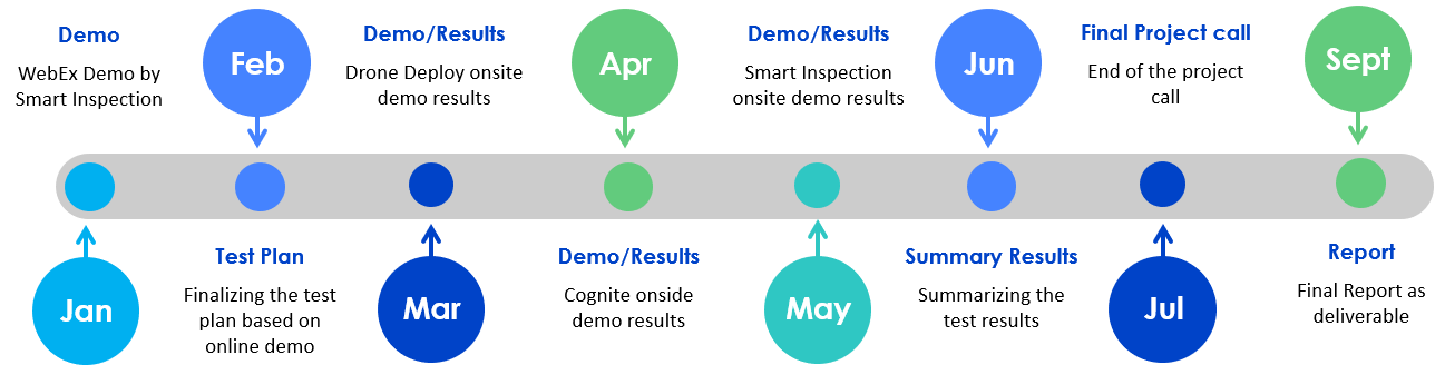
Evaluation of Substation Robotics Analytical Platform in Lenox – Test Plan
The goal is to ensure successful integration between the Spot’s systems and the analytical software. The test plan will attempt to capture using teleoperation and autonomously. Functionalities related to the command & control, fleet management, data workflows, analytics, software deployment, cybersecurity, and other requirements.
Testing Results – Quick update videos
Based on the listed features, robot analytics software vendors were/will be invited to Lenox to test their software solution for 2-3 days. This testing includes remote teleoperation, autonomous path planning, analog gauge reading, thermal inspection, and emergency stop.
Meeting Materials
WebEx Project Update: End of the year webcast – 30th Nov. 2023
1 - Functional Specifications for an Autonomous Substation Robot Analytics Software
Introduction
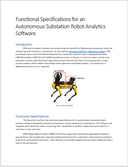
EPRI and its project members are researching the feasibility of deploying autonomous robots for monitoring and inspection in substations. At the end the Substation Robotics Application project, EPRI purchased a Spot robot from Boston Dynamics for substation research. Spot is equipped with Spot CAM+IR and Spot CORE I/O with LiDAR payloads (as shown in Figure 1). Currently, Spot is performing autowalk missions and collecting imagery data (visual and thermal). Each mission generates a large amount of data, which needs to be categorized to generate actionable insights. To achieve this, a dedicated analytical tool is required.
Figure 1: Spot Payloads
Functional Specifications
This document outlines the functional specifications for an autonomous substation robot analytics software designed to enhance autonomous visual inspections in substations. The software will integrate with substation robots, improving their capabilities to perform inspections and analytics in real-time or near real-time.
EPRI Subject Matter Experts (SMEs) and utility researchers have jointly developed functional specifications that include both required and desired features for a substation robot analytical platform to perform autonomous operations. These features are broadly categorized into seven categories with a total of 63 sub features:
Command and Control: This category focuses on providing operators with the tools and capabilities to remotely control and monitor robots. It includes features such as teleoperation, real-time data visualization, autonomous path planning, and the ability to return to home automatically.
Fleet Management: This category is centered around efficiently managing a fleet of robots. It involves tracking the location and status of robots, scheduling maintenance, updating firmware, monitoring network and cybersecurity, and integrating with legacy systems.
Data Workflows: This category streamlines the organization, sharing, and analysis of data collected by the robots. It includes features such as data organization, data conflation, data sharing, image annotation, metadata management, and supporting AI-based decision-making and alert/notification systems.
Analytics: This category focuses on extracting insights and performing analysis on the collected data. It includes integrations with existing APIs, intelligent focus, various inspection capabilities (visual, thermal, acoustic, etc.), and custom applications tailored to specific needs.
Software Deployment: This category deals with the different deployment options for the software, including on-premises, cloud-based, hybrid, or edge deployments. It also encompasses the choice between software-based or browser-based interfaces.
Cybersecurity: This category ensures the security of data and operations. It includes features such as encrypted communication and storage, secure networking, user permissions, multi-factor authentication, and support for single sign-on.
Other Requirements: This category encompasses additional functional requirements such as the type of data processing (real-time or batch), ease of use for the software interface, and compliance with regulations like GDPR for data protection.
For more detailed explanation for each feature and sub feature is provided in the spreadsheet Functional specification document or use the interactive plot below. Just hover on to each category and it will pop up an explanation to each category.
Figure 2: Functional Specifications. Please note when hovered on each feature it shows the explanation for the feature, you can also click each category to get better view of each category
Member Ratings
The functional specification document was provided to each utility lead, who were then asked to rate each sub-feature/technology using the following rating system as shown in table below.
Research/Pilot phase
Rating System
I know I need that
4
I think I'm going to need this
3
I may want this
2
I don't think I need this
1
I know I don't need it
0
Each utility lead, along with their team, provided their input based on this rating system. The ratings were then average across all utility responses. Later, the ratings were further categorized into three priority levels based on the following criteria as shown in table below.
Ratings
Priority
3 <=
High
2 > & < 3
Medium
2 >=
Low
Among the 63 features members rated 25 as high priority (required features), 23 as medium priority (desired features), and 15 as low priority (not required). The final categorization based on priority was color-coded and displayed in the interactive plot below.
Figure 3: Member Ratings Summary
Vendor Ratings
EPRI conducted interviews with 14 different vendors from around the world., some of which have branches in the US. The interviewed vendors include Alisys, Boston Dynamics, Chironix, Cognite, DroneDeploy/ROCOS, Energy Robotics, Formant.io, IDB, Levatas, Mitsubishi, Percepto, Plain Concepts, Roboverse Reply, and Smart Inspection. During the interviews vendors were given the opportunity to demonstrate their software capabilities, with some vendors even providing live demos with their robots in office environments.
Vendors were then asked to rate their software capabilities for each feature using the following rating system shown in Table below. Out of the 14 vendors, EPRI received responses from 11.
Response
Rating
This feature is available in our software, and we could demo it
Fully implemented
This feature is beta stage, and we could demo this feacture as beta version
In development
Thies feature in not available in our software, and it is part of our road map
Planned
This feature in not available or not in our road map but can be customized
Needs customization
We do not have this feature and are not planning tp have it in future
Not applicable/not supported
The vendor ratings provide insights into the availability and development stage of different features within their software offerings. Please use the interactive plot below which allows you to hover onto each vendor ID to see Vendor Ratings and are color-coded and displayed.
Figure 4: Vendor Ratings Summary
Evaluation
EPRI utilized a specific approach to evaluate the vendor responses alongside member ratings. The vendor ratings, originally provided as qualitative responses, were translated into numerical values as follows: Fully Implemented – 4, In development – 3, Planned – 2, Needs customization – 1, Not applicable/Not supported – 0.
Rating
Rating System
Fully implemented
4
In development
3
Planned
2
Needs customization
1
Not applicable/not supported
0
For the evaluation, only the high and medium priority features were considered based on member ratings. Certain Q/A features such as “Any other applications?”, “Ease of software use”, “Type of data processing”, and “Software vs. Browser-based” were removed, resulting in a total of 47 features for evaluation.
To calculate the final evaluation scores, member ratings and vendor ratings were multiplied by the average member rating for each category, using the following formula:
The resulting evaluation score were plotted in an interactive plot that allows users to hover over each vendor ID to view their vendor ratings. The scores were color-coded for clarity.
Figure 5: Vendor Evaluation Summary
The table below provides a summary of the total evaluation values for each category, with the highest values highlighted in yellow.
Vendor ID
Analytics
Command and Control
Cybersecurity
Data Workflows
Fleet Management
Other
Software Development
Total
VID 6
85.25
131.25
93
90.5
60.5
13
19
492.5
VID 4
92.25
114
84.75
115.25
63.75
13
9
492
VID 11
85
127.5
84.25
106.25
63
9.75
11.5
487.25
VID 8
74.75
120
93
120.5
52.75
13
9
483
VID 1
85.25
120.5
69.75
106.25
59.5
13
16.75
471
VID 5
101
112.5
75.5
102
46
13
16.75
466.75
VID 3
74.75
95
74.25
83.75
65.75
13
19
425.5
VID 10
25.25
101.75
93
93.75
63
9.75
19
405.5
VID 9
47
97.75
74.5
94
59.75
6.5
9
388.5
VID 2
60.25
111.5
55.5
95.75
28.25
6.5
14.5
372.25
VID 7
82.5
0
68.5
85
3
0
19
258
2 - Evaluation of Substation Robotics Analytical Platform in Lenox - Test Plan
Day 1:
During day 1 the software platform setup time and communication setup will be recorded. Basic teleoperation functionalities and emergency stop functionalities will be tested out.
Schedule
Introduction
a. Safety overview – Lenox, 138 kV yard and Spot, weather brief, photos in Lenox
b. EPRI summary of events and schedule with contingency options
c. Vendor overview and explanation of software
Software Integration with Spot
Check the hardware and payload compatibilities and integrate the software with the Spot.
Configure and verify communication path (radio/Wi-Fi/LTE).
Test the communication and the Spot’s parameters.
Brief the team the UI and some of the settings.
a. Various camera settings, battery percentage, health performance.
b. Different camera view, BIM model, LiDAR model
Visualization with and without LiDAR model. How does it look?
Teleoperation
Undock the spot using software interface and drive to an identified test location.
Test sit and stand option.
Walk the Spot forward, backward, sideways, clockwise, and anti-clockwise.
Demonstrate various ways to control spot – keyboard, joystick, click-to-go, etc.
Test the emergency stop functionality.
Demonstrate the payload registration process with SV600 payload.
a. change of frequency band, bin, etc.
Demonstrate image quality and resolution. Quality of video can be changed
Dock the spot back in its docking station.
Demonstrate the spot settings such as high step walking, roll over, obstacle avoidance limit, walking speed, change in height, ground friction, collision avoidance, etc.
Teleoperation - Analytics Testing – Energized Yard
Walk spot to a gauge to test the gauge reading model.
Walk spot to PD source and test the Acoustic detection functionality.
Demonstrate the various settings available for performing Acoustic detection like change of frequency band, bin, etc.
Walk spot to change detection (if applicable) to demo the functionality.
Walk spot to transformer tank heating and test the thermal inspection and few common settings that can be configured during autonomous inspection.
Demonstrate communication with existing APIs like battery monitoring data.
Demonstrate deployment of docker container through the software (if applicable).
Download and test if the data (pictures, videos, audio, and sound) is being recorded and check its quality.
Autonomous Route
Prepare for autonomous operation of 138 kV yard.
Program the mission using tablet/or transfer to Software as shown in Figure below.
Note: Program autonomous route through software if possible.
Run the Spot one lab around the yard with the programmed route and inspection points.
Test Setup
Day 2:
During day 2 the focus will be running autonomous missions with testing the analytics functionalities.
Schedule
Introduction (new member guests)
a. Safety overview – Lenox, 138 kV yard and Spot, weather brief, photos in Lenox
b. EPRI summary of events and schedule with contingency options
Round One – Yard not Energized
Spot Auto-walk Inspection Loop – as programmed on day 1 – expectation is that Spot captures pictures with Spot CAM and SV600 payloads at preset waypoints.
Inspection Loop
Start the mission from the Dock House
Spot stops at preset waypoints as programmed
Spot poses the SV600(and other payloads) in one or more directions and captures data
Spot moves back to the Dock House and uploads the captured data.
Demonstrate the data collected using the autonomous mission and options of visualizing the data.
Demonstrate the Data sharing, Data annotation capabilities, and user metadata
Round Two – Yard Energized
Trigger the autonomous loop using software
Perform the inspection loop
While the loop is in progress, check if estimated time remaining is available.
Review the data captured during the inspection loop
Replay the logs captured while the spot is in autonomous mission
Round Three – Yard Energized
Trigger the autonomous loop using software
Perform the inspection loop
While the loop is in progress test “Return to Home (Loss link, Low battery)” by creating a fault in network connection and having the battery drain while the mission is autonomous.
Return to home via low battery and loss link.
Round Four – Yard Energized
Trigger the autonomous loop using software.
Perform the inspection loop.
Trigger emergency stop.
Continue the mission or teleoperate to the docking station.
Round Five – Yard not Energized (Staged Defects/Analytics: Thermal Inspection, Analog Gauge Reading)
Heat the oil in tank 1
Modify the mission parameters to read the gauge and read the thermal inspection data.
Configure the notification and alarm when the value reaches above threshold.
Trigger the autonomous loop using software
Perform the inspection loop.
Observe the alarm or notification process and document if the alarm is immediate or is it after the mission.
Round Six – Yard not Energized (Staged Defects/Analytics: Air leak detection, Change detection, PD detection, Oil leak)
Setup the oil leak scenario, and air leak using compressor.
Modify the mission parameters to detect the oil leak.
Configure the notification and alarm when the value reaches above threshold.
Trigger the autonomous loop using software.
Perform the inspection loop.
Observe the alarm or notification process and document if the alarm is immediate or is it after the mission.
Observe the alarm or notification process and document if the alarm is immediate or is it after the mission.
Night Testing: During night testing the focus will be running autonomous missions while testing the analytics functionalities during nighttime with and without external lights.
Round Eight – Yard Energized (SpotCAM lights ON)
Night job safety briefing.
Enable the spot onboard lights using software.
Trigger the autonomous loop using software.
Perform the inspection loop.
Enable two way communication and test the functionality using software.
Observe the alarm or notification process and document if the alarm is immediate or is it after the mission.
Round Nine – Yard Energized (SpotCAM lights OFF)
Keep the SpotCAM lights ON during the start of the mission.
disable the spot onboard lights using software.
Trigger the autonomous loop using software.
Perform the inspection loop.
enable the spot onboard lights using software while the Spot is in DGA alley
Day 3:
During day 2 the focus will be running repeated autonomous missions and perform on-demand inspection while testing the analytics functionalities.
Schedule
Introduction (new member guests)
a. Safety overview – Lenox, 138 kV yard and Spot, weather brief, photos in Lenox
b. EPRI summary of events and schedule with contingency options
Round One – Yard Energized
Trigger the autonomous loop using software.
Perform the inspection loop.
Round Two – Yard Energized
Trigger the autonomous loop using software.
Pause the mission while the spot is in mission.
Teleoperate spot to different location and perform on-demand inspection i.e., have spot read a new gauge.
Resume the mission.
Round Three – Yard Energized
Deploy the docker container using software on the spot to read the battery data.
Trigger the autonomous loop using software.
Monitor the docker values if possible, using software.
Perform the inspection loop.
Round Four, Five, Six – Yard Energized
Reorder the inspection points in the autowalk and trigger the mission.
Select/deselect inspection points and trigger the mission.
Change the mission parameters, inspection point parameters and trigger the mission.
Round Seven to twelve – Yard Energized
Setup the mission for scheduling the mission for every 15/30 minutes.
Trigger the autonomous loop using software.
Perform the inspection loop.
Wrap up – Conference room
Transfer all the data collected from the Spot and software
Demonstrate other capabilities of software.
Demonstrate Intelligent focus vs autofocus capabilities if available.
Demonstrate software’s API capabilities or custom development.
Demonstrate if any AI – post-processing is available on the data collection – Object detection
Demonstrate the Data organization over time.
Demonstrate the fleet management capabilities such as Legacy integration, maintenance schedule, robot tracking, firmware update
Demonstrate cyber security features such as user permissions, and others if available.